Generally speaking, the design of gating systems follows three principles:
1. Rapid pouring: to reduce temperature drop, recession and oxidation;
2. Clean pouring: avoid the generation of slag and impurities, and shield the slag in the molten iron from the cavity;
3. Economic pouring: maximize the process yield.
1.The location of the choke section
1. When designing the pouring system, the first thing to consider is the position of the flow blocking section, because it determines the filling speed. Generally speaking, there are two traditional locations for arranging choke sections.
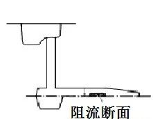
2.One is to arrange it between the lateral runner and the inner runner. The number may be consistent with the number of the inner runner. It is also called pressure pouring. Since the minimum cross-section is close to the casting, the linear speed of the molten iron is very high when it enters the cavity.
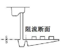
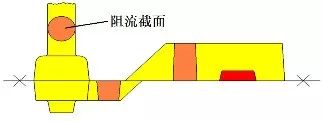
3.The other is placed between the sprue and the lateral runner, with only one flow-blocking section, also called pressureless pouring.
4.Modern cast iron production is inseparable from filtration technology. In order to better apply foam ceramic filters, the sprue should be used as a flow blocking section in process design.
Factors to consider
1.Pouring time, this is one of the functions of the pouring system, and there are various algorithms. Nowadays, simulation software is mostly used to calculate it. So is there any faster way to calculate by hand? Answer: Yes, and it’s simple.
T sec =√(W.lb)
Among them: t is the pouring time, the unit is seconds, W is the pouring weight, the unit is pounds. Keep it simple.
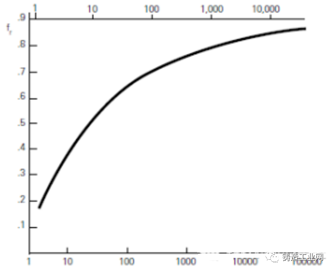
2. Friction coefficient. The molten iron will rub against the mold wall during pouring. Friction will also occur between the molten iron and there will be energy loss, so it must be considered.
Generally speaking, for thin-walled plates, the friction coefficient § should be as small as 0.2; for thick and square parts, the friction coefficient§should be as large as 0.8.
3.Of course, you can also be more precise. The chart below can be used to find it.
Post time: May-07-2024


